


OCP Global Summit 2026 | TE Connectivity | Sakina Naqvi, Usman Saeed | Co-Packaged Copper at 448G
1. Why This Talk Matters: The Same Company, Talking About the Cost
TE Connectivity gave more than one talk at this OCP; a separate OIF-related session covered the 448G electrical interface itself. We explained why 448G is the dividing line in ECOC 2026: Three Hours of Fast-Narrow vs Slow-Wide, and the Dividing Line Is 448G.
This session was presented by TE System Architect Sakina Naqvi and Principal System Architect Usman Saeed, and the title itself is a trade-off: electrical efficiency versus system-level complexity. Attendees had heard about the benefits of CPC for two days; what made this talk unusual is that a company that sells CPC spent half its time explaining how hard CPC is to build.
The slides put three architectures side by side:
Traditional motherboard: the package runs a long PCB trace to the I/O connector, which is very hard to fit into the 448G channel budget.
NPC (near-packaged copper): the connector sits on the board next to the package; the trace is shorter but still consumes budget.
CPC (co-packaged copper): the connector is mounted directly on the package, so the SI channel budget contains no PCB segment.
Naqvi framed it pragmatically: CPC is not a new technology, but familiar high-speed connectors and low-loss copper cable moved closer to the ASIC.
2. Breaking Down the Electrical Advantage: The Gap Comes From 100 mm of Trace
Start with the media. TE compared 250 mm of 30AWG twinax with 254 mm of stripline at 112 GHz:
Medium | Length | Insertion loss at 112 GHz | Approx. per cm |
Twinax 30AWG | 250 mm | ~4 dB | 0.16 dB |
PCB stripline | 254 mm | ~23 dB | 0.91 dB |
(Per-cm figures are STT calculations from the slides.) At the same length, PCB loss is 5.75 times that of cable. Saeed's explanation: PCB is limited by layer thickness and has higher skin-effect loss, while twinax is fully shielded and has better crosstalk.
Next, the full channel. TE's two simulations are cleanly designed: CPC runs 350 mm of cable straight from the package; NPC uses 250 mm of cable plus 100 mm of PCB trace. Total length is the same; the difference is whether the first 100 mm next to the ASIC is cable, or a board connector plus PCB.

▲ Over the same 350 mm channel, CPC loss is only half that of NPC for both backplane PAM6 and front-panel PAM4; the gap comes from the 100 mm closest to the ASIC (PCB trace plus motherboard connector) (Image source: Simple Tech Trend original; data from TE Connectivity 2026 OCP Global Summit presentation)
Channel | Modulation | Nyquist | CPC | NPC | Gap |
CPC/NPC to backplane | PAM6 | 90 GHz | ~6 dB | ~12 dB | 6 dB |
CPC/NPC to front-panel I/O | PAM4 | 112 GHz | ~7 dB | ~14 dB | 7 dB |

▲ TE's simulated 448G backplane channel: at 90 GHz, CPC is about 6 dB and NPC about 12 dB, with NPC carrying an extra 100 mm of PCB trace (Image source: TE Connectivity | 2026 OCP Global Summit presentation)
Saeed's conclusion: the 448G link budget is already tight, and NPC at 448G is "likely going to be quite challenging to implement", while CPC makes PAM4 to the front panel feasible.
Two caveats up front. First, neither simulation includes package loss. Second, these are simulations, not measurements; Saeed said evaluation boards and measurements are still in progress.
3. Cost One: The Connector Becomes Part of the Package
Naqvi then moved the discussion from dB to assembly. CPC solves the ASIC "escape" problem by sending high-speed signals from the package straight into twinax. But the slide continues: the cable and connector system now becomes part of the ASIC package itself, so all components must be designed together.
There are three challenges:
Connector tolerances: on the package, even the smallest deviation can keep contacts from mating. Tolerance stack-ups must be done at the assembly level, not just the component level.
Cable strain: 448G means more signals and more cables, and cable forces must not transfer into the package. In Naqvi's words, the package is a very important piece of the tray.
Package warpage: materials in the stack-up have different coefficients of thermal expansion and move differently in operation, yet alignment must hold over the full lifetime.
The more fundamental issue is geometry: bandwidth and I/O density keep rising while the ASIC package perimeter barely changes. Saeed said a single system already has thousands of differential pairs.
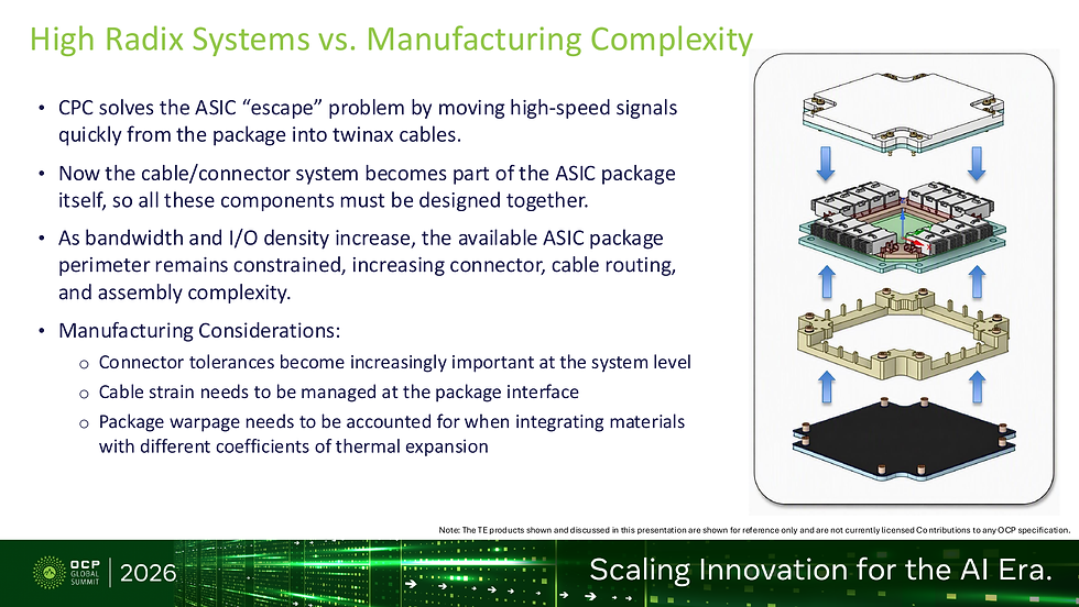
▲ The CPC stack-up: the connectors around the package, the retention frame and the upper and lower boards must be designed together, with tolerances, cable stress and warpage all handled at the package level (Image source: TE Connectivity | 2026 OCP Global Summit presentation)
Naqvi said TE's goal is not the densest solution, but one that can be manufactured, assembled, cooled and serviced. That amounts to an admission: density is not CPC's bottleneck, manufacturability is.
4. Cost Two: Heat and Skew Spend Part of the Margin Again
Heat. Traditional connectors sit some distance from the ASIC; CPC sits inside the ASIC's thermal environment. TE's data: for a 1 m cable, loss (in dB) rises 3% to 5% for every 10°C; from 20°C to 90°C insertion loss grows by about 2.4 dB, and that excludes the connector.

▲ Heating a 1 m cable from 20°C to 90°C raises insertion loss by about 2.4 dB, or 3% to 5% for every 10°C (Image source: TE Connectivity | 2026 OCP Global Summit presentation)
STT rough estimate: if the entire 350 mm CPC cable sat at 90°C, scaling by length adds about 0.84 dB, roughly 14% of the 6 dB backplane advantage. In practice only the section near the package is hottest, so this is an upper bound. The key point is TE's requirement: SI channel models cannot be run only at room temperature; they must cover operating temperature and thermal cycling.
Skew. 448G is very sensitive to bend radius. If the positive and negative conductors of a pair see different radii of curvature in a bend, their path lengths differ and intra-pair skew appears; a 45-degree twist does the same. The practice is to follow every bad-way bend with an equal and opposite bend, but that is hard to fit in dense systems.
TE's chart shows a fixed skew consumes timing budget linearly with baud rate: 1 ps is 10% of a UI at 100 GBd and 20% at 200 GBd.

▲ A fixed 1 ps skew takes about 11% of a UI at 224G, about 18% at 448G PAM6 and about 22% at 448G PAM4; 5 ps already exceeds one UI at 448G PAM4 (Image source: Simple Tech Trend original; data from TE Connectivity 2026 OCP Global Summit presentation)
Converting with the slides' Nyquist frequencies (baud equals twice Nyquist), the same 1 ps of skew costs twice the timing budget at 448G PAM4 as at 224G, and about 1.6 times at PAM6. That is why TE prioritizes low-skew cable and low-Dk foam-like dielectrics; some customers prefer cables with drain wires precisely because they are stiffer and harder to bend.
5. CPC Is a Rehearsal for CPO Package Integration
The last technical slide is titled "CPC as a Natural Transition to CPO". TE makes two points:
CPC and CPO can share a common reference architecture for front-panel or backplane connectivity.
The package-level electrical, mechanical and thermal integration practices built with CPC can support a future transition to CPO.
Naqvi added a caveat: this does not mean every CPC system will easily transition to CPO, only that the process becomes smoother. Her other line was blunter: optics is inevitable, as the expo floor shows.
This matters more than it looks. The hardest part of CPO is not only the optical engine but the mechanics, heat and assembly around the package. CPC lets connector makers enter the package layer in the copper era, so when CPO arrives, they are already at the table. This is consistent with the copper-optics coexistence timeline we discussed in After Copper Runs Out for AI: Seven Paths for Scale-Up Optical Interconnect. STT's view: in the 448G generation, copper retreats to the package edge to last one more generation.
6. Risks and Counterarguments
Simulation only: the 6 dB and 7 dB gaps are simulated and exclude package loss. TE showed a CPC-to-backplane demo at its booth, but evaluation-board measurements are not yet public, and TE's own call to action asks the industry to share channel-level SI data.
Risk concentrates on the most expensive part: with the connector on the package, any assembly or cable-strain problem affects the whole ASIC; the slides did not address rework.
Perimeter is a hard limit: with a fixed package perimeter and ever more pairs, CPC's density ceiling is ultimately set by geometry, which is also the argument for CPO and optical I/O.
NPC is not necessarily ruled out everywhere: TE's conclusion targets long channels such as backplane and front panel. For very short internal runs, Saeed himself said cableless CPC is possible, and different topologies may have different answers.
No standard yet: every slide notes the products shown are not licensed contributions to any OCP specification; CPC interfaces remain each vendor's own design.
7. What It Means for Taiwan's Supply Chain
The talk named no Taiwanese companies; the following covers industry positions only.
PCB loses a segment of the 448G high-speed path: in TE's simulation, the difference between NPC and CPC is that 100 mm of trace. High-speed signals leaving the PCB is a long-term variable Taiwanese server and switch board makers need to take seriously; power, control and low-speed signals stay on the board.
Packages and substrates carry more responsibility: CPC makes the package carry connectors, retention frames and cable strain as well as the die, raising requirements on warpage and CTE matching. For ABF substrate and OSAT players this is a spec upgrade, and possibly a new assembly step.
Twinax and cable assembly are incremental: low-loss, low-skew, heat-tolerant twinax and cable management at the package are core CPC materials. Taiwanese cable assemblers who want in need 448G-grade skew control and SI measurement capability at elevated temperature.
Thermal modules must be co-designed with connectors: TE explicitly cited cold-plate and cable mechanical loads, so Taiwanese liquid-cooling and cold-plate makers need to co-design with connector makers rather than deliver separately.
Further reading: 2026 OCP APAC Summit: CPO / NPO / XPO Panel.
8. Conclusion
The value of TE's talk is that it laid out both sides of the CPC trade-off. One side is 6 to 7 dB of margin, enough to make NPC very hard to close on long 448G channels; the other is that the connector stops being a board component and becomes part of the ASIC package, bringing tolerances, warpage, heat and skew into package design.
On timing, there are only simulations so far, evaluation-board measurements are ongoing, and there is no interface standard. Over the next 12 months, watch three things: whether measured channel data from TE and its peers match the simulated 6 dB gap, whether connector makers or OSATs lead CPC assembly, and whether any 448G platform publicly adopts CPC.
At 448G, copper is not losing to optics; it is being forced into the package. Whoever learns to build connectors on the package first gets the first ticket to CPO.
This article is for technology and industry trend analysis only and does not constitute investment advice.


Comments