


The Optical Packaging Transition (Part 5): The Detachable Fiber Battle, CPO's Hidden Gating Factor - How Teramount, Senko, Intel and ICON Each Solve It
CPO technical presentations typically spend 90% of their time on how the EIC and PIC are stacked, how the grating coupler is designed, and how good 3D hybrid bonding yields look. But step onto a data center ops floor and the first question from operations engineers is simple: "Can you replace the fiber?"
It sounds like a naive question, but it is the real gating factor for CPO volume production. Pluggable optics dominated for a decade largely because when one fails, you pull it out and swap it. No matter how low the failure rate, hyperscalers will not accept tearing down an entire switch and sending it back to the OSAT for rebonding just to replace one fiber. Once CPO moves optics into the ASIC package, this serviceability problem is magnified instantly.
The industry has reached consensus: the fiber-to-chip connection must be detachable. But there is no consensus on how. Teramount, Senko, Intel and ICON Photonics each have their own approach, layered on top of a deeper contest among V-groove, edge coupler and grating coupler optics. This connector standards battle will decide whether CPO truly goes mainstream after 2027–2028.
1. Why Detachability Is CPO's Hidden Gating Factor
First, the pain point. A 102.4T-class CPO switch may carry 8–16 optical engines, each needing 16–64 fibers. A single package may have hundreds to thousands of fiber connections. In the data center:
Fibers fail: anyone who ran ops in the pluggable era knows that a dirty connector, an exceeded bend radius or a bump during a move can take out a single fiber
CPO packages can't be taken apart: once EIC-PIC hybrid bonding is done and the optical engine is soldered to the substrate, the package is one-shot; if it fails, the whole multi-chip module must be replaced
Failure blast radius: if one bad fiber takes a whole 102.4T switch offline, hyperscalers lose millions per minute
Without a detachable fiber solution, CPO stays stuck at the pilot stage forever.
That is why progress from Teramount, Senko, Intel and ICON on connectors matters more than any EIC-PIC stacking headline. They are solving whether CPO can leave the lab at all.
2. Teramount: Solving Alignment with a Two-Stage Optical Interface
Teramount has the most complete solution structure, with four elements:


Bump: an optical protrusion added to the PIC wafer, made with a wafer-level process and handled by the OSAT
Plug Fiber Connector: takes in light from the FAU and redirects the optical path vertically
Mirrors: mirrors inside both the Bump and the Plug Connector widen alignment tolerance by 10x
Mechanical socket: a mechanical part that holds the FAU and SiPh die together while keeping them detachable
The key idea is the two-stage optical interface. Conventional fiber-to-chip uses direct butt coupling, which requires sub-micron alignment. Teramount routes light through a reflection and uses mirror tolerance design to relax alignment to a much friendlier range. That matters for CPO volume production, because a production line can't do active alignment on every unit.
Pros: wafer-level integration, wide tolerance, can be handled by the OSAT in back-end assembly.
Cons: the vertical optical path adds extra loss (mirror reflectivity can't be 100%), and the overall form factor is somewhat larger than direct edge coupling.
3. The Senko + Aerotech + Santec Alliance: Active Alignment on the Production Line
Senko takes the opposite path. Rather than widening tolerance through optical design, it uses active alignment to push positioning accuracy to the limit. The solution is a three-company collaboration:
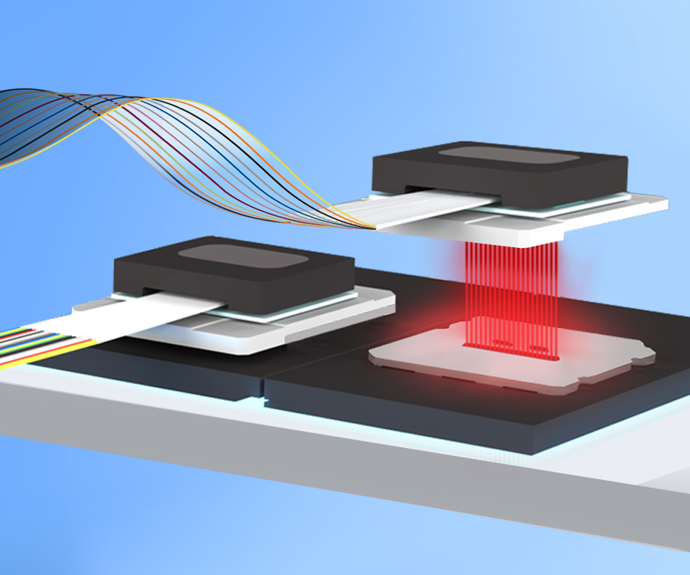
Aerotech: 6-axis ultra-precision motion stages with real-time control for sub-micron alignment
Santec: tunable lasers, power meters and spectral monitoring that provide optical feedback for closed-loop alignment
Senko: high-precision fiber arrays and ferrules that form the mechanical interface to the PIC
Capability specs of the full solution:
Lateral alignment accuracy: ±0.1–0.2μm
Vertical alignment accuracy: ±0.1μm
Angular alignment accuracy: <0.1°
Coupling loss: on par with state-of-the-art edge coupling
Repeatability: sub-micron, production-grade
Pros: extremely high alignment accuracy, best coupling efficiency, repeatable (controllable in production).
Cons: every PIC needs active alignment, cycle times are longer, and it requires expensive motion stages and optical instruments. It looks more like a pilot-to-mid-volume solution than one for millions of units.
4. Intel: Redefining the Interface with Chiplet Logic
Intel's OCI approach reframes the fiber-to-chip problem. Instead of designing a better connector, Intel turns optical I/O into a detachable chiplet interface: the optical interface travels with the OCI chiplet, and fiber attaches to the chiplet rather than directly to the ASIC die.
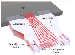
The advantage of this approach is decoupling: replacing fiber touches only the OCI chiplet, not the ASIC; ASIC generations can change while keeping the same fiber interface; and different customers' ASICs can connect to the same OCI. It's also a business model for Intel: it sells the whole chiplet, not a fiber connector.
Pros: architectural decoupling, high flexibility for future upgrades, aligned with chiplet standards such as UCIe.
Cons: it needs ecosystem adoption. Today it is mainly used on Intel's own platforms, and other ASIC vendors' willingness to adopt it is still unproven.
5. ICON Photonics and Other Players
ICON Photonics is a relatively young French player targeting the detachable fiber-to-chip connector niche. Few details of its approach are public, but it is listed as one of the main candidates, competing in a design space similar to Teramount's.
Other relevant players:
MicroAlign: high-precision multi-fiber active alignment, focused on quantum applications
Diamond Photonics: alignment and mechanical interfaces
Bay Photonics: a UK OSAT doing quantum-related fiber attach
The market is wide open right now, with no single company holding dominant share. That means the standard isn't locked in yet, and the first solution to reach volume production could become the de facto standard.
6. The Underlying Optics Battle: V-Groove vs Edge vs Grating
Beyond connector design, the deeper question is which path light takes from fiber into the waveguide. The three mainstream approaches each have strengths:
Dimension | V-groove | Edge Coupler | Grating Coupler |
Mechanism | Etched V-grooves for mechanical alignment, used with edge couplers | Fiber end face butts against the waveguide at the chip edge | Grating diffracts light vertically into the waveguide |
Coupling loss | Depends on coupler design, best <1 dB | Best <1 dB | 2–3 dB and up |
Bandwidth | Widest (120 nm) | Wide (<100 nm) | Narrow (20 nm, improvable) |
Alignment tolerance | Moderate (1–5μm) | Strict (<1μm) | Relaxed (up to 10μm) |
Polarization sensitivity | Depends on coupler | Can be designed for low sensitivity | 1D grating sensitive, 2D better |
Wafer-level test friendliness | Medium | Harder | Most friendly |
Manufacturing cost | Low (passive alignment in volume) | High (requires facet polishing) | Medium |
The table shows each approach has its own winning ground. TSMC's COUPE platform publicly supports both grating and edge coupling precisely because both have customers: hyperscalers prefer grating (production-friendly), while high-performance needs favor edge (low loss).
V-groove will keep evolving in the CPO era: fiber pitch is shrinking from the traditional 250–260μm to 127–130μm, doubling the number of fibers per mm of edge. That directly determines whether multi-Tb/s/mm bandwidth is achievable. Early SiPh pluggables needed only 4/8 fibers, 800G modules use 8/16, 1.6T optical engines jump to 16/32, and a CPO switch edge may need 16–64 fibers across multiple FAUs. Shrinking pitch is unavoidable.
7. Photonic Wire Bonding: Elegant in Theory, Still Early
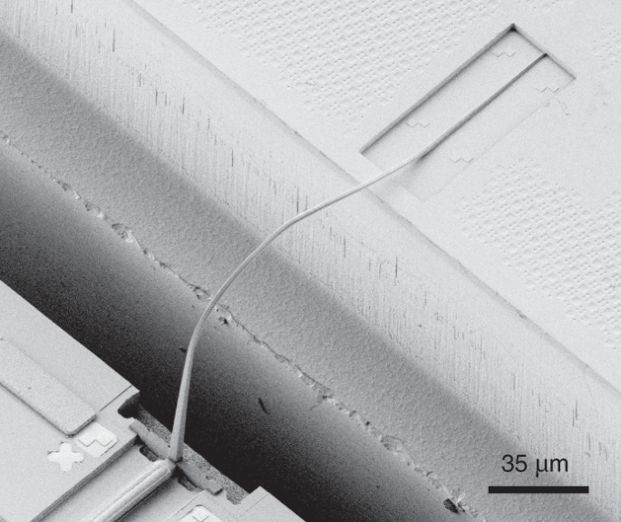
A word on Photonic Wire Bonding (PWB), driven by Vanguard Automation (part of Mycronic) and Nanoscribe. It uses two-photon polymerization to "print" optical waveguides directly between chips so light can pass across.
Theoretical advantages:
Can connect different dies (laser die to PIC, PIC to PIC, fiber to photodiode)
No strict alignment needed (software adjusts the print path)
Can fabricate nanostructures and prisms at the same time
In reality, the technology is still mostly in research labs. Volume use faces open questions: how long printed polymer survives thermal and mechanical stress, material compatibility, and whether print speed can keep up with production throughput. It won't be a mainstream CPO solution in the short-to-medium term, but it may find its first foothold in high-value, low-volume markets such as quantum and sensors.
8. Quantum Is the Other Extreme: Coupling Loss Must Approach Zero
In optical communications packaging, loss is measured in dB and 1 dB is acceptable. Quantum packaging plays by entirely different rules: each photon carries a qubit, and once it's lost it's gone; it can't be amplified or recovered.
That puts fiber alignment requirements on another level:
Grating couplers are out (2–3 dB loss is too much)
Passive edge coupling lacks enough alignment tolerance
Standard telecom-grade fiber arrays fall short on single-photon fidelity and long-term phase stability
MicroAlign's high-precision multi-fiber active alignment and Diamond Photonics' integration of color-center quantum emitters onto ultra-low-loss platforms are the two most prominent solutions today. The market is small but strategically valuable: quantum interconnects and quantum networks (quantum repeaters) will depend on this chain long term.
9. Conclusion: Connector Standards Are CPO's Hidden Deciding Factor
Back to where we started: CPO's hidden gating factor for volume production is whether you can replace the fiber.
The industry agrees connections must be detachable, but how is still contested. Teramount's two-stage optical interface, the Senko alliance's active alignment, Intel's chiplet approach, and ICON's French solution: four paths coexist, on top of competition among V-groove, edge and grating optics. This standards battle will gradually be settled over 2026–2028.
For hyperscalers, the choice affects long-term data center ops cost. For ASIC designers, it must be locked in at chip-level layout and can't be changed later. For the packaging supply chain, it decides where back-end packaging line equipment investment goes.
This axis is often underestimated in CPO discussions because it sounds too mechanical, too engineering-heavy, not sexy enough. But in every interconnect transition in history, from ISA to PCI, SCSI to SATA, RJ45 to SFP, establishing the connector standard was what truly brought the technology into the mainstream. CPO will be no exception.


Comments