


OCP Global Summit 2026 | Lightelligence, AMD | Bobby Lu, Ron Swartzentruber | Short Reach Optical Interface for Scale-up
1. Why These Two Speakers Matter
This was the opening talk of the SROI session at the OCP Future Technologies Symposium on October 14, 2026. Both speakers co-chair the SROI workstream: Bobby Lu is a Principal Engineer at Lightelligence, a photonic computing and optical interconnect company, and Ron Swartzentruber is from AMD.
The pairing is itself a signal. AMD is the demand side: Swartzentruber used AMD's own Helios rack as the example, noting that once several Helios racks are joined into a pod, each rack needs tens of thousands of optical lanes, which copper cannot deliver. Lightelligence represents the optical supply side.
The white paper took three years. Swartzentruber admitted he expected it to take one. Against the slide's 12–18 month accelerator generation cycle, that works out (STT calculation: 36 months ÷ 12–18 months) to two to three accelerator generations passing before the requirements were published. The slides make the same point twice: the window is narrow.
2. Breaking Down Reach: 1–30 m Was Undefined Territory
SROI's first contribution is a clean reach taxonomy. Existing optical classes leave a gap between 10 cm and 500 m:
Class | Reach | Defined by |
In-package OIO | < 1 cm | — |
XSR / VSR | 1–10 cm | OIF |
SROI | 1–30 m | OCP (this white paper) |
DR | 500 m | IEEE |
FR | 2 km+ | IEEE |
Scale-up sits right in that gap. The slides define scale-up as reach under 30 m, round-trip time under 1 µs, about 1,000 GB/s per XPU, and memory (load/store) semantics; scale-out is under 2 km, under 10 µs, and about 400 Gb/s.
The speakers argue that DR/FR datacenter optics solve the wrong problems: long-distance fiber attenuation, dispersion compensation, OSNR budgets, and complex equalization and DSP. In Swartzentruber's words, lighting up those optical lanes today burns nearly as much energy as copper does. SROI instead optimizes four things: optical lane density at the package edge, energy per bit, cost per lane at rack-scale volume, and the reliability memory-semantic fabrics require. It is also protocol-agnostic: UALink, ESUN, PCIe Gen7, CXL and NVMe share the same physical layer.

▲ SROI fills the gap between 10 cm and 500 m; copper reaches about 3 m at 200G and only about 1 m at 400G (Image source: Simple Tech Trend original; data from Lightelligence and AMD, 2026 OCP Global Summit presentation)
3. Breaking Down the Four Thresholds: Power Is Nearly There, Two Others Are an Order of Magnitude Off
This slide is the single most important takeaway from the talk:
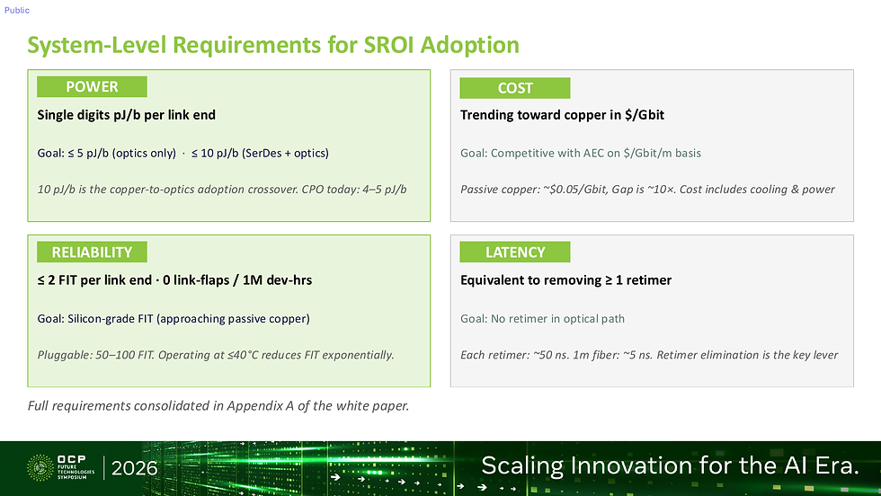
▲ SROI's four system thresholds: power, cost, reliability and latency (Image source: Lightelligence, AMD | 2026 OCP Global Summit presentation)
Put the targets next to the current-state figures the slides themselves give:
Item | SROI target | Current state per slides | Gap (STT calculation) |
Power | Optics ≤5 pJ/bit; SerDes + optics ≤10 pJ/bit | CPO 4–5 pJ/bit | Already within target |
Reliability | ≤2 FIT per link end; 0 link flaps per 1M device-hours | Pluggables 50–100 FIT | 25–50x |
Cost | $/Gbit/m competitive with active electrical cables (AEC) | Passive copper about $0.05/Gbit, gap about 10x | About 10x |
Latency | No retimer in the optical path | About 50 ns per retimer | Architecture-dependent |

▲ The gaps on SROI's four thresholds: power is already met, CPO reliability is 5–10x short, cost about 10x, and pluggable reliability 25–50x (Image source: Simple Tech Trend original; data from Lightelligence and AMD, 2026 OCP Global Summit presentation)
A few numbers worth converting:
Power: the slides call 10 pJ/bit the copper-to-optics adoption crossover. At 1,000 GB/s per XPU (about 8 Tb/s, STT assumes one direction), 10 pJ/bit is about 80 W per end, or about 80 kW on the XPU side alone for a 1,000-XPU pod. With CPO already at 4–5 pJ/bit, power is no longer the main obstacle.
Reliability: the slides say CPO FIT is 5x better than pluggables, which STT converts to about 10–20 FIT, still 5–10x above the ≤2 FIT goal. The slides also point to one lever: operating at or below 40°C reduces FIT exponentially.
Cost: a 10x gap implies optics at about $0.50 per Gbit. As a rough STT estimate, a 1.6T link costs about $80 in copper versus about $800 in optics. The slides note that cost includes cooling and power.
That explains why Bobby Lu spent the most time on reliability. His example: in a shared-memory architecture, one bit flip or link drop can mean anything from retraining a session to the whole system going down for hours while engineers hunt for the failed optical segment.
4. Breaking Down Latency: One Retimer Equals 10 m of Fiber
The slides give two numbers: about 50 ns per retimer and about 5 ns per meter of fiber.
In other words, removing one retimer frees up the latency budget of 10 m of fiber. Thirty meters of fiber is about 150 ns one way and 300 ns round trip, already about 30% of the 1 µs RTT budget (STT calculation). There is little room left for retiming.
This target maps directly onto the technology options:

▲ SROI's three-phase deployment model: power, FIT, bandwidth and serviceability of pluggable, NPO and CPO (Image source: Lightelligence, AMD | 2026 OCP Global Summit presentation)
Now: pluggable LPO at 5–6 pJ/bit and RTLR at 8–10 pJ/bit, bandwidth from 1.6T to 3.2T+, field-replaceable at the front panel.
1–2 years: NPO (CPX MSA) at about 5 pJ/bit (linear), 6.4T moving to 12.8T, repaired by opening the box and removing the board.
2–3+ years: CPO (CPX MSA) or OCI MSA BiDi, 4–5 pJ/bit with PAM4 and 3 pJ/bit with DWDM, factory repair only.
STT's reading is that RTLR (retimed transmit, linear receive) is awkwardly placed: at 8–10 pJ/bit it exceeds the ≤5 pJ/bit optics target, and its retimer conflicts with the latency goal. It can serve as a bridge in the pluggable era, but it is not the end state within the SROI framework. Only retimer-free linear options (LPO, NPO, CPO) meet the latency goal, and LPO at 5–6 pJ/bit still sits slightly above the power target.
This matches the conclusion of our earlier piece ECOC2026 | Fast-and-narrow vs slow-and-wide: scale-up optics is decided at the SerDes on the chip edge: the bottleneck is pushed back to the electrical interface at the chip edge.
5. Breaking Down the Nomenclature: What Exactly Is NPO?
SROI worked with OIF and other standards bodies to unify the names for where optics are placed. It sounds like paperwork, but the speakers stressed how much effort it took, because the point is a shared language: when someone says NPO, there should be data that pins down what it means.
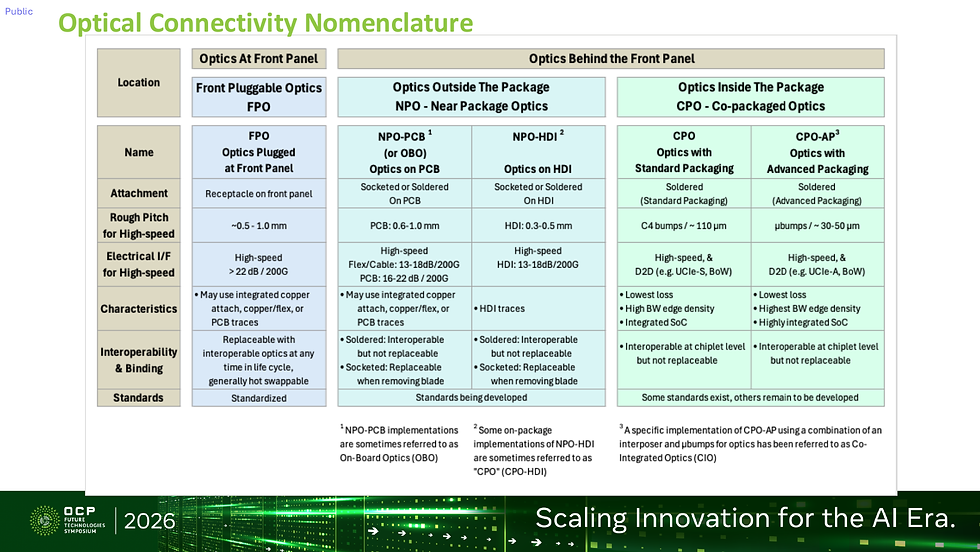
▲ SROI's optical connectivity nomenclature: pin pitch and electrical interface loss for FPO, NPO-PCB, NPO-HDI, CPO and CPO-AP (Image source: Lightelligence, AMD | 2026 OCP Global Summit presentation)
The table separates five placements by high-speed signal pitch:
FPO (front-panel pluggable): about 0.5–1.0 mm, hot-swappable, standardized
NPO-PCB (also called OBO): PCB pitch 0.6–1.0 mm, socketed or soldered
NPO-HDI: HDI pitch 0.3–0.5 mm; some on-package NPO-HDI implementations get called "CPO"
CPO: C4 bumps at about 110 µm, die-to-die interfaces such as UCIe-S and BoW
CPO-AP: µbumps at about 30–50 µm, UCIe-A; the interposer-plus-µbump variant is also called CIO
The most useful part is that footnote: some products marketed as CPO are, by this table, actually NPO-HDI. When reading vendor decks, ask about pitch and attachment method first and you will know which box they belong in.
6. Risks and Counterarguments
The white paper is a set of requirements, not a spec. SROI is still a Future Technologies workstream; the speakers said they are working to graduate it to a formal OCP work group. The thresholds only bind once IEEE 802.3, OIF or JEDEC adopt them.
≤2 FIT may be too strict. The goal is silicon-grade reliability approaching passive copper, but lasers are active components. If the industry instead buys system reliability with spare lanes or multi-lane fault domains, the component FIT threshold may be renegotiated.
The cost-gap method is not disclosed. The roughly 10x figure comes without its basis, such as whether cooling, power and yield are included; the slides only say cost includes cooling and power.
The 400G optical path is not settled. The slides say silicon photonics plasma-dispersion bandwidth is too low for 400G PAM4, requiring hybrid InP or LiNbO₃, while OCI MSA follows an NRZ-plus-WDM slow-and-wide roadmap. The two paths mean different things for the SROI thresholds.
7. What It Means for Taiwan's Supply Chain
Before 400G, copper still has room inside the rack. The slides' copper reach table shows passive copper at about 1–1.5 m at 200G/lane and 2.5–3 m with a retimer; at 400G PAM4 it drops to about 1 m, and CPC is likely the only viable topology. For Taiwan's copper cable and connector makers, the question is how many in-rack links CPC can win in the 400G generation. Another detail: copper favors PAM6 and optics favor PAM4, so gearbox SerDes designs will diverge.
NPO-HDI and CPO-AP pitches fall into substrate and advanced packaging territory. HDI at 0.3–0.5 mm and µbumps at 30–50 µm belong to HDI boards and advanced packaging respectively, both areas where Taiwan has a complete industry. With unified naming, suppliers can target the right box earlier.
Reliability thresholds will become a qualification business. SROI plans tiered reliability frameworks: CPO would borrow AEC standards (not elaborated on the slides; the appendix lists AEC alongside Telcordia and JEDEC as qualification standards, which STT takes to mean the Automotive Electronics Council, distinct from the active electrical cable AEC in the cost row), while pluggable scale-up gets a new baseline. For optical module manufacturers and test houses, FIT and link-flap qualification capability will matter as much as capacity.
Further reading: OIF draws an official map for AI interconnect covers OIF's energy-efficiency requirements, and 2026 OCP APAC Summit | SemiAnalysis | Scale Up Sophistry discusses the copper-optics boundary from a cost angle.
8. Conclusion
The talk launched no product, but it delivered a report card for scale-up optics, graded by the demand side. The result is clear: power has passed, pluggable reliability is 25–50x off, and cost is about 10x off.
That changes what to watch. For the past two years the industry has competed on pJ/bit; for the next two it will compete on FIT and $/Gbit. Until those close, the reason optics enters scale-up will be that copper cannot reach, not that optics is better. The first wave of demand is in inter-rack pods beyond 3 m, and in-rack copper only gets truly pushed out at 400G/lane.
Power is no longer the bottleneck for scale-up optics; reliability and cost are. Until they catch up, optics will only appear where copper cannot reach.
This article is for technology and industry trend analysis only and does not constitute investment advice.


Comments