


Datasheet fs Numbers Can Mislead You: What Six 312.5 MHz Clocks Reveal About the 1.6T/3.2T Clock Bottleneck
As optical modules move to 1.6T and 3.2T, the phase purity of the reference clock becomes, for the first time, a variable that decides whether the link fails. But when you open oscillator datasheets and see numbers like 17 fs, 25 fs, 30 fs, 38 fs and 72 fs, at least two things can mislead you. First, they may not be measured with “the same ruler,” or may not even be the same class of product. Second, what decides whether a module passes is how much of the clock's jitter is left after the receiver equalizer, not the bare datasheet number. This article benchmarks six real 312.5 MHz-class clock devices (three quartz XOs, one MEMS XO, one BAW clock IC and one synthesizer IC, all identified by codename), working from phase noise and jitter all the way to near-compliant TDECQ. The result is a practical evaluation framework, and a counterintuitive conclusion: at today's 224G/lane the differences are small but starting to show; only at the next baud node does the clock take over.
To avoid naming specific vendors and part numbers, this article uses codenames throughout: S-company, E-company and K-company (quartz XO), T-company (MEMS XO), W-company (BAW clock IC) and R-company (synthesizer IC).
1. Why the clock goes from supporting role to lead as baud rises
For the past decade, when optical module engineers picked a reference clock, “cheap, right frequency, works” was roughly enough. That era ends with the 1.6T/3.2T generation.
The reason is that the jitter budget, measured in UI, is collapsing. 224G/lane means 224 Gb/s; with PAM4 that is 112 GBd (symbol rate), with a Unit Interval (UI) of only 8.93 ps. PAM4 also splits each UI vertically into four levels and three sub-eyes, each only one third the height of an NRZ eye. Squeezed horizontally by baud and vertically by PAM4, the tolerance left for jitter is pushed to the limit. Across SerDes clock-chip application notes, the integrated phase jitter requirement for reference clocks at 224G/lane is already down to the 25–35 fs RMS range, a 3–5x cut from the relaxed 100–150 fs of the 112G/lane generation.
More importantly, the architecture is changing. To save the power of a per-lane CDR (Clock Data Recovery), new-generation PHYs are moving toward forwarded clocking. The 256 Gb/s silicon photonics DWDM link presented at ISSCC/ECTC 2026 deliberately makes the clock and data paths symmetric so jitter is tracked passively. The side effect: removing the CDR pushes the jitter line of defense forward to the oscillator itself. If the source clock is dirty, nothing downstream cleans it up. We analyzed this forwarded-clock stack in detail in Technical Analysis | NVIDIA Lays Out Its Full “Optics into the Interposer” Stack: From ECOC Concept to ISSCC Production
.
A speaker in the OFC 2026 session on 1.6T line-side technology put it bluntly: as baud rate rises, you need not just narrow laser linewidth but “a very pristine type of phase noise control.” That applies to lasers, and it applies equally to reference clocks.
The clock wasn't promoted to a lead role; baud rate forced it there.
2. How clocks are made: quartz, Si MEMS and BAW
To read a datasheet, you first need to know how the clock is generated. Three types of resonator compete in the market, and their differences set the ceiling on phase noise.
Quartz and BAW use direct resonance: the resonator oscillates close to the output frequency, so output purity is nearly that of the resonator itself. AT-cut quartz has a Q of tens of thousands to over a hundred thousand; BAW (Bulk Acoustic Wave) resonates directly at GHz. Neither needs much frequency multiplication.
Si MEMS uses indirect synthesis: the native frequency of a MEMS resonator is usually only tens of MHz, so a fractional-N PLL multiplies it up to 100/156.25/312.5 MHz. The problem lies in that multiplication: phase noise is amplified by 20·log₁₀(N). Each doubling raises noise by 6 dB, on top of the PLL's own in-band noise and fractional spurs. This is physics, not a yield issue.
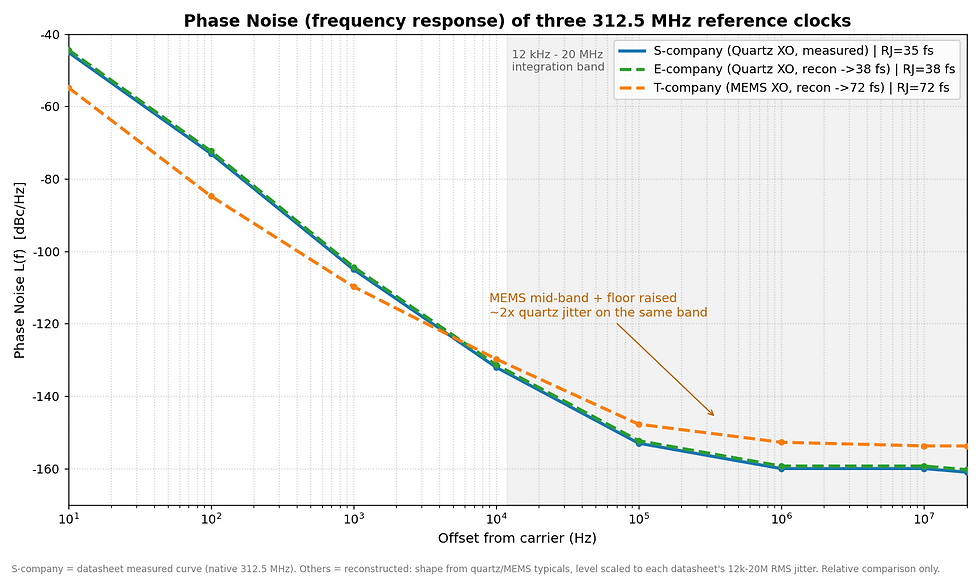
That is why, over the same integration band, conventional Si MEMS has roughly twice the jitter of quartz. It's not that the silicon resonator is bad; the “low-frequency resonator + large PLL” synthesis chain raises the noise floor.
Two side notes. First, MEMS also drifts in frequency: silicon's temperature coefficient of frequency is about −30 ppm/°C (tens of times that of quartz), so it relies on on-chip temperature sensing and digital compensation, and imperfect compensation leaves residual drift and hysteresis. Second, BAW can reach ultra-low jitter on silicon (BAW clocks are rated as low as 17 fs) precisely because it resonates directly at GHz with almost no multiplication, bypassing the MEMS synthesis chain. It isn't an “improved MEMS” at all; it uses different resonator physics.
The differences among these three approaches can be seen in one diagram: where the resonator comes from, whether PLL multiplication is needed, and where each lands in jitter:

Overlaying their actual phase noise (frequency response) makes the difference more concrete:
3. Impact on signal integrity: from phase noise to the eye diagram
Phase noise is not an academic number. It eats into your link along two paths.
Path one: phase noise → random jitter (RJ) → eye closure → higher bit error rate. Integrating phase noise over 12 kHz–20 MHz gives RMS phase jitter, which divided by the carrier frequency becomes time jitter (fs). This jitter is a common/correlated component that the CDR may not track out, and the residual directly eats horizontal eye width.
Path two: frequency drift → ppm offset → CDR tracking burden. MEMS temperature drift and hysteresis consume the frequency-offset budget between transmitter and receiver, and force the CDR to keep re-tracking as temperature changes, degrading jitter tolerance.
To translate jitter into real impact, the common engineering bridge is: at BER 1e-12, peak-to-peak total jitter (TJ) ≈ 14.07 × RJ (RMS). That is why a clock that looks like “only a few tens of fs” gets magnified into a noticeable loss of eye width inside a 224G UI. In the next section we run this chain end to end with six real products.
4. Benchmark: six 312.5 MHz-class clocks head to head
The lineup expands to six devices across four approaches, all in the reference clock class for 400G/800G/1.6T optical modules:
Quartz differential XOs (the mainstream for this socket):
S-company (quartz differential XO): native 312.5 MHz, LVDS, 3.3 V, −40 to 105°C, ±25 ppm, phase jitter 30 fs typ / 50 fs max (12k–20M), 38 mA, 2.0×1.6 mm.
E-company (quartz differential XO): SPXO + temperature-compensation IC, 25–500 MHz, ±20 ppm (including 10-year aging); headline 38 fs typ @156.25; in its per-band spec, the >212 MHz band is 50 fs max.
K-company (quartz differential XO): a high-capacity new challenger (recently in volume production) with industry-leading 30 fs, going head to head with S-company.
MEMS XO:
T-company (MEMS XO): silicon MEMS resonator, programmable differential XO, 50–625 MHz multi-frequency, multiple outputs, adjustable swing, PSNR 9 fs/mV. The headline claims 41 fs, but that uses the vendor's own narrow-band algorithm (4 MHz high-pass / 16 MHz low-pass); over the same standard 12k–20M band it is 72 fs typ / 100 fs max.
IC class (integrated resonator or synthesizer, not a bare XO):
W-company (BAW clock IC): integrated Bulk Acoustic Wave (BAW) resonator, 17 fs class, aimed squarely at 224G and coherent.
R-company (synthesizer IC): 25 fs-rms system-level figure, explicitly supporting 112G/224G SerDes.
First, the key specs of all six side by side:
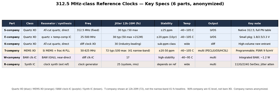
This is where the first trap gets amplified: fs numbers are only comparable with “the same ruler,” and you have to know which class of product you are looking at first. T-company's 41 fs is a narrow-band algorithm; 72 fs is the same-band (12k–20M) figure. W-company's 17 fs and R-company's 25 fs are IC/system-level numbers, not bare XOs. Placing them next to quartz XOs at 30/38 fs is comparing a “system report card” to a single component. Aligning bare XOs on the same band, the ranking is S-company 30 ≈ K-company 30 < E-company 38 < T-company 72; adding the IC class, the lowest are W-company BAW 17 < R-company 25.
What data we used:
S-company: datasheet phase noise table + jitter (native 312.5).
E-company: datasheet 156.25 phase noise plot + per-band jitter (>212 MHz band, 50 fs max).
K-company / T-company / W-company / R-company: each vendor's officially published headline 12k–20M (or equivalent) jitter (30 / 72 / 17 / 25 fs).
Assumptions:
All phase noise plots are reconstructed curves: the shape follows the typical characteristics of each approach (quartz/MEMS/BAW/synthesizer), and the overall level is calibrated to the product's headline 12k–20M RMS jitter, not point-by-point measurements.
TDECQ calculations use 224G/lane = 224 Gb/s = 112 GBd, UI 8.93 ps (next node, 448G/lane = 224 GBd).
The measurement chain is an IEEE-style 4th-order Bessel-Thomson reference receiver filter (3 dB = 0.5×baud) + 5-tap T-spaced MMSE RxFFE.
σ_eq is taken at two slices, 0.45 and 0.55 UI, with a target of SER 2.4e-4 (KP4 FEC RS(544,514), Qt = 3.414); TDECQ = 10·log₁₀(σ_ideal / σ_eq), σ_ideal = OMA_outer / (6·Qt).
TDECQ for all six is computed by feeding only each headline jitter through the same pipeline, counting only the reference clock contribution (no laser RIN/ER, single lane). It is a near-compliant illustration, not a lab compliance measurement. W/R-company are IC-class, a different product class from bare quartz/MEMS XOs, and are shown alongside only for jitter-magnitude comparison.
In one sentence: the datasheet fs is a starting point, not the end. First confirm the measurement band matches, then confirm it is the same class of product, and only then work out its real impact on the eye.
5. Trap two: the clock only counts after the equalizer
Now for the most counterintuitive, and most valuable, part.
First, how to read a PAM4 eye diagram and TDECQ. PAM4 has four levels, stacked into three sub-eyes. The horizontal axis is time in UI; one UI is one symbol period (8.93 ps at 112 GBd). The three white dashed lines D0/D1/D2 are the decision thresholds the receiver uses to separate the four levels. The two cyan dashed lines are the TDECQ measurement points (0.45 and 0.55 UI); the standard specifies how much the eye closes at these two slices.
TDECQ (Transmitter Dispersion Eye Closure Quaternary) uses a single dB figure to describe how much a transmitter's eye is closed compared with an ideal eye. The method finds a noise level σ_eq that, when added, just passes at the target SER (2.4e-4), and compares it with the noise σ_ideal an ideal transmitter could tolerate. Higher TDECQ = more closed eye = worse; the compliance limit for the 400G-DR4 / 800G per-lane class is 3.4 dB.
Here is the key point. We first computed with only the BT reference filter and no RxFFE: all six eyes were closed (TDECQ off the chart). That isn't the clock's fault. A 0.5×baud reference filter by itself crushes a 112 GBd PAM4 eye to invisibility, which is exactly why the TDECQ measurement method requires a 5-tap receiver equalizer.
So we add a 5-tap MMSE RxFFE, the equalizer recovers the eye, and the real numbers emerge:
312.5 MHz product | Class | TDECQ @112 GBd (BT4 + 5-tap RxFFE) |
W-company (17 fs) | BAW clk-IC | 1.04 dB |
R-company (25 fs) | Synthesizer IC | 1.04 dB |
S-company (30 fs) | Quartz XO | 1.04 dB |
K-company (30 fs) | Quartz XO | 1.04 dB |
E-company (38 fs) | Quartz XO | 1.04 dB |
T-company (72 fs) | MEMS XO | 1.07 dB |
See the issue? The six headline jitters span 17 to 72 fs (more than a 4x spread), yet after the standard BT + RxFFE their TDECQ contributions are all packed into 1.04–1.07 dB, well within the 3.4 dB limit. The equalizer absorbs most of the jitter difference between reference clocks. Even so, the MEMS XO option comes out slightly higher, by 0.03 dB. At today's 224G/lane, from a TDECQ standpoint, reference clocks are starting to make a small difference in product performance. With AI data centers demanding extremely high quality and low power from optical modules, that 0.03 dB may no longer be the 0.03 dB it used to be. You also have to weigh their other differences (lead time, frequency flexibility, vibration resistance, PSNR, cost). Lead time in particular: with optical communications products under intense demand pull, conventional MEMS solutions will face challenges too.
6. Trap three: the clock's importance only explodes at the next baud node
Stopping the story at “the clock isn't the bottleneck” would mislead you, because that conclusion carries a hidden condition: 112 GBd.
Push the same calculation to the next baud node, 448G/lane, i.e., 224 GBd with the UI halved to 4.46 ps, and the gap opens up:
Product | Class | TDECQ @112 GBd | TDECQ @224 GBd |
W-company (17 fs) | BAW clk-IC | 1.04 dB | 1.04 dB |
R-company (25 fs) | Synthesizer IC | 1.04 dB | 1.05 dB |
S-company (30 fs) | Quartz XO | 1.04 dB | 1.05 dB |
K-company (30 fs) | Quartz XO | 1.04 dB | 1.05 dB |
E-company (38 fs) | Quartz XO | 1.04 dB | 1.09 dB |
T-company (72 fs) | MEMS XO | 1.07 dB | 1.25 dB |
(Reference) poor clock, 259 fs | — | 1.66 dB | Eye closed / fail |
Double the baud and the UI halves, so the same absolute jitter (fs) takes up twice the share of the UI, and the equalizer struggles more and more to recover it. Only at 224 GBd does a ranking emerge: W-company (BAW) holds rock-steady at 1.04, R/S/K-company at 1.04–1.05, E-company at 1.09, T-company at 1.25. BAW and top-tier quartz pull ahead at the next baud node. And a poor 259 fs clock that is still usable at 112 GBd (1.66 dB) closes the eye outright at 224 GBd, beyond what the FFE can recover.

This answers the opening question, “why do clocks matter more and more beyond 1.6T/3.2T?” The answer: small differences begin to appear in the 1.6T era, and by 3.2T the clock spec drives much more of product performance. If you are choosing a clock for 800G/1.6T today, the six differ little. But if you are reserving design margin for platforms beyond 3.2T, with single lanes heading past 200 GBd, reference clock purity is make-or-break. That is why ultra-low-jitter quartz and BAW (17 fs class) are staking out the top-tier slot. For where this path leads, see our discussion of higher-baud generations in Breaking the Bottleneck with Plasmonics: The Lifeline Beyond 3.2T.
7. Conclusion
The three traps add up to a practical evaluation framework:
First, when you see an fs number, ask “which ruler, which product class?” Narrow-band algorithms and 12k–20M can't be compared directly (T-company's 41 fs and 72 fs are two ways of describing the same part), and IC-class 17/25 fs can't be placed directly beside bare-XO 30/38 fs.
Second, judge jitter after the equalizer. At 224G/lane, after standard BT + 5-tap RxFFE, TDECQ for all six converges to ~1.04 dB, with differences still slight (MEMS a bit higher).
Third, the clock's importance explodes with baud. The gap only opens at 448G/lane, where a poor clock fails outright.
For part selection, first separate product classes. For top-tier purity at 224G/448G, W-company's BAW (17 fs) and R-company's synthesizer IC (25 fs) are the IC-class answers. At the bare-XO level, S-company and K-company tie for best at 30 fs quartz, with E-company at 38 fs next. If you need frequency flexibility, short lead times, vibration and thermal robustness, and the best PSNR, T-company trades “roughly 2x the jitter” for that system value, a cost that barely affects TDECQ at today's baud. Just remember its real number is 72 fs (12k–20M), not the 41 fs on its homepage.
The bigger point: in this industry, the reference clock has long been an overlooked component, because it's cheap and because the equalizer has always been cleaning up after it. But baud rate won't stop. As single lanes push beyond 200 GBd, the equalizer's eraser keeps getting shorter. When that day comes, the “least noticeable part” you choose today will be the first to decide whether your optical module passes.
One last necessary caveat: all phase noise curves, jitter conversions and TDECQ figures in this article rest on a chain of assumptions and simple mathematical calculations (see the data and assumptions in Section 4). TDECQ also counts only the reference clock contribution, excluding the laser and a real optical channel. The value of this benchmark is in the relative magnitudes and the evaluation framework, not in absolute compliance numbers.
If any step is miscalculated or any assumption is unreasonable, corrections are very welcome. More complete measured data (especially official 312.5 MHz phase noise tables from each vendor) is also welcome; I can rerun the same model to make this comparison more accurate.
References
Datasheets for 312.5 MHz-class reference clock products from each vendor (quartz differential XO, MEMS XO, BAW clock IC, synthesizer IC).
Application notes on SerDes reference clock jitter requirements (112G / 224G PAM4).
IEEE Std 802.3, TDECQ measurement method and reference receiver (Bessel-Thomson + RxFFE) definitions, Clauses 121/122.
OFC 2026, MW2 “Market Status and Enabling Technologies of 1.6 Tbps and Beyond” session notes.
Related reading
From ECOC Concept to ISSCC Production: The Full Optics-into-the-Interposer Stack: how the forwarded-clock architecture pushes the jitter line of defense back to the source.
Why DWDM Laser Arrays Rewrite the Economics of Optical Interconnect: the implementation context for passively tracking clock jitter.
Breaking the Bottleneck with Plasmonics: The Lifeline Beyond 3.2T: signal integrity challenges in higher-baud generations.


Comments