


ECOC 2026 | Data Centers Need Billions of Lasers — and the Bottleneck Is the 5 Minutes It Takes to Attach Each One
On the first Sunday morning of ECOC 2026, the organizers ran a 3.5-hour workshop with 11 speakers: Su1-A/Su2-A, "Light sources for next-generation optical communication systems for AI datacenters." The first half brought in Cignal AI, Oracle, Huawei, AMD and Columbia University to discuss system requirements; the second half invited UBC, Quintessent, Photon Bridge, NTT, Chalmers and III-V Lab to cover device technology.
Lay the slides from both halves side by side and it becomes clear that what this workshop was really arguing about was not "which laser is better" at all.
The light-source conversation has switched tracks: from "how well does this laser perform" to "where does this laser live, how do you replace it when it fails, and can you make billions of them." The organizers' very first slide drew the inward path from scale-out → scale-up → CPO/NPO → optical I/O, and stated bluntly that "this scale changes the entire debate about light sources."
80% of the cost isn't the laser chip — it's packaging, assembly and test. UBC's Lukas Chrostowski put numbers on it: active alignment plus curing takes 5–10 minutes per connection; eight channels means 40–80 minutes of serial assembly. That is the real ceiling on "billions of lasers."
The ink on two specs is still wet: OCI 200G Line Interface v1.0 landed on March 11, 2026, and Open CPX v1.0 on September 16, 2026 — four days before the workshop. The industry is using standards to lock in the "external light source" path first.
But "slow and wide" throws the problem back to the laser. To do 8λ, 16λ, 32λ or even 128λ, the laser turns from "a component" into "an entire subsystem"; Quintessent, Photon Bridge, Chalmers and NTT offered four completely different solutions.
The real value of integration is 18 dB. NTT settled the math with one optical power-budget chart: an external high-power source must start at +15.5 dBm, while an integrated membrane laser needs only −2.5 dBm — and almost the entire difference is eaten by the 9 dB of a 1×8 splitter.
1. Why this workshop matters: the light-source conversation has changed
The organizers — Abdul Rahim (PhotonDelta), Despoina Petousi (ADTRAN), Wei Shi (U Laval) and Wilfried Maineult (Coherent) — made their position clear from the start. The second slide was titled "Scale Changes the Debate," with a left-to-right timeline: scale-out (rack to rack) → scale-up (inside the supernode) → CPO/NPO (next to the switch chip) → optical I/O (next to the XPU).
Optics is moving inward toward the compute core one step at a time. And with every step inward, the number of optical connections in the same system jumps from "thousands" to "tens of thousands."
When the order of magnitude changes, the evaluation criteria change with it. The organizers' line is worth quoting in full: the question is no longer the performance of the light source itself, but "how to use a given light source within a given system architecture while delivering performance, scalability, and the right cost point."
That slide also carried a deliberately blank table, with columns for SiPh + CW Laser / VCSEL / MicroLED and rows for energy efficiency, effective reach, latency, cost per bit and technology maturity. The whole workshop was an attempt to fill in that table.

2. The demand side was blunt: they don't want the performance champion, they want the one that doesn't fail
The four demand-side organizations in Session I argued from completely different angles, but their conclusions were strikingly consistent.
Cignal AI's Scott Wilkinson set out the scale. By 2030, annual shipments of 400G-and-above data center optical modules will exceed 160 million; 800G shipments peak in 2027–2028 at more than three times the 400G peak; ELSFP external light-source modules (8 lasers each) grow from about 250,000 units in 2026/27 to more than 4 million in 2030; CPO ports grow from about 1 million in 2026 to about 33.5 million in 2030; and OCS ports exceed 40 million in 2030.
He also added a sting: InP demand has already caused a global shortage, and some vendors claim they will triple or quadruple InP capacity within 18 months. We broke this thread down in full in You Can Ban Modules, but Not Substrates: The Optical Battle Has Moved Down to Indium Phosphide.

Oracle's Mark Filer delivered the most concrete "lesson learned" of the day. OCI's AI clusters have grown from 16,384 GPUs in 2020 to 131,072 GPUs in a single cluster today, NIC speeds have gone from 25 Gbps to 1,600 Gbps, and effective network cluster performance has grown 256x. At this scale, he called out an underestimated problem: laser mode hopping.
Mode hopping causes sudden wavelength shifts, SMSR degradation and uncorrectable bit errors, ultimately showing up as link flaps. Oracle's recommendations were specific: for pluggable modules using uncooled lasers, manufacturing should replace "fixed-temperature-point measurement" with "temperature and current sweeps," monitor SMSR and wavelength at the laser, CoC and module stages, and finally confirm with module-level temperature cycling plus traffic testing; to control cost, focus first on the 45–70°C case temperature range.
He also debunked an industry myth: CW lasers are actually low-FIT components. Citing Meta's OCP 2025 data, the failure Pareto for 400G FR4 (mostly EML-based) is dominated by manufacturing issues (PCBA, wire bonding), with very few laser diode failures; Google's data states it even more directly: "no laser reliability failures — firmware is the No. 1 issue." The notion that "the laser is the least reliable component in the system" comes from experience with directly modulated lasers (DML/VCSEL) and shouldn't be applied to CW lasers.

AMD's Haisheng Rong mapped the numbers to the rack level. The Helios open rack: 2.9 EFLOPS of compute, 31 TB of HBM4, 260 TB/s of scale-up bandwidth and 43 TB/s of scale-out bandwidth. The efficiency ladder is straightforward: pluggable modules >15 pJ/bit, on-board optics (OBO) about 10–15 pJ/bit, CPO about 5 pJ/bit — roughly a 3x improvement.
Huawei's Zhang Shiyong showed what is already running. In 2025, Atlas 900 paired 384 NPUs with 6,912 × 400G SR8 (VCSEL + oDSP); in 2026, Atlas 950 switched to 4,096 × 800G SR8 VCSEL LPO, scaling to thousands of NPUs, with official claims of 90% lower latency and 60% lower power. He also showed a 3.2T NPO optical engine demo: 4 × (8 × 100G/lane), 50 m over OM4, 13.7 W, about 4.3 pJ/bit.

3. The real bottleneck: 80% of the cost isn't the laser
The first speaker in Session II, UBC professor and Dream Photonics CEO Lukas Chrostowski, titled his talk in two sentences: "Data centers need billions of lasers. Connecting the lasers is the bottleneck."
He broke laser manufacturing into six steps — materials, wafer processing, device test, packaging, alignment and curing, and final test — alongside a donut chart: the chip itself is 20% of the cost; packaging, assembly and test are 80%.
Worse is the cycle time. The optical path in a conventional butterfly package is "collimate → isolate → focus into fiber," requiring sub-micron active alignment. His numbers: the alignment plus epoxy-curing cycle is about 5–10 minutes per connection; eight channels means 40–80 minutes of serial assembly.
Multiply that by Cignal AI's 4 million ELSFPs at 8 lasers each and the answer is clear: this path doesn't get you to 2030.

His solution moves the precision from "component placement" to "optical connection": build and test the laser and the photonic chip separately, measure their actual positions after placement, then 3D-print the matching lens on the spot. Dream Photonics' target is a throughput of 5 million connections per tool, with coupling loss below 1.2 dB.
This "rather than aligning more precisely, make misalignment not matter" approach is on the same line as our earlier pieces on Teramount's CPO patents and Fiber-to-Chip: The Least Sexy Step in CPO That's Blocking Everyone.
He also shared something few people say publicly — on choosing between hybrid and heterogeneous integration, he cited Intel's lesson: choose hybrid until sales volume reaches a threshold; the risk of going heterogeneous too early is "more than $100 million in R&D you never recover, plus an expensive process and thin margins."
4. Where should the light source live: three locations, three failure risks
Chrostowski's fifth slide laid out the options in three columns: pluggable transceivers (replace the whole module), CPO + external light source (replace the ELSFP, keep the CPO and compute), and lasers built into the CPO (he put a big red X on this column, annotated "failure risk? or an opportunity for on-chip lasers in socketized CPX?").
The point isn't which performs better; it's "how expensive a thing you have to replace when it fails."
That's also why two specs are landing at the same time:
OCI 200G Line Interface v1.0 (March 11, 2026): 4λ per direction, 8λ total bidirectional on a single fiber, Group A starting at 1308.00 nm and Group B at 1327.69 nm, with about 2.3 nm (400 GHz) adjacent spacing, at 53.125 GBaud NRZ. AMD added the ELSFP hard specs: absolute wavelength accuracy ±0.2 nm, RIN −144 dB/Hz, linewidth <1 MHz, case temperature 40–60°C.
Open CPX v1.0 (September 16, 2026, four days before the workshop): 6.4/7.2 Tbps, 32/36 lanes, up to 212.5 Gbps per lane, explicitly defining two light-source options — the integrated laser module (ILM) and the external laser module (ELM/ELSFP) — and unifying a single socket aligned on mechanical, electrical, optical, thermal and CMIS.
We wrote a full breakdown of Open CPX: Breaking Down Open CPX 1.0: CPO Finally Gets a Standard Socket.
Interestingly, the demand side and the device side diverged here. Chrostowski put an X on "lasers inside CPO," yet Oracle explicitly stated "for NPO/CPO, we prefer integrated lasers (assuming feasible)," reasoning that human mishandling of transceivers is the No. 1 failure mode in the data center, and CPO/NPO takes people out of deployment and operations; moreover, ELSFP pluggability may be a liability rather than an asset — blind-mate connectors are hard to clean and hard to inspect, and once contaminated the whole unit is scrapped.
This split wasn't resolved at the workshop. It will be resolved by field failure data over the next two years. For context, see The Most Fragile Link in CPO Is the Laser.

5. "Slow and wide" throws the problem back to the laser
Columbia University's Keren Bergman quantified the system pain points with an efficiency ladder: in-package (GPU–HBM4, 25.6 TB/s) under 50 fJ/bit; scale-up (NVLink 6.0, 3.6 TB/s per GPU) about 5 pJ/bit; scale-out (1.6 Tbps NIC per GPU) over 20 pJ/bit. Going from the compute package out to fiber, efficiency drops by two orders of magnitude.
Her case is for "wide": the optical domain can pack multiple channels into the same waveguide and the same pin, a dividend the electrical domain can't get. Columbia's own 3D photonic I/O achieves 5.3 Tb/s/mm², 80 channels TX+RX, 25 µm pad pitch, Tx 70 fJ/bit and Rx 120 fJ/bit.
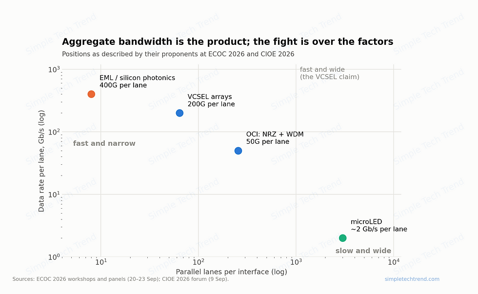
Chalmers' Victor Torres-Company spelled out the narrow & fast vs wide & slow trade-off even more plainly: the former has low complexity (no MUX) but is limited by ISI and high-baud-rate power, and clock recovery is tricky; the latter has better receiver sensitivity, can use CMOS drivers and micro-ring modulators, supports clock forwarding and has better latency (no FEC, no DSP), at the cost of requiring multiple wavelengths. We compared this axis in full in After Copper Can't Keep Up with AI: Seven Paths for Scale-Up Optical Interconnect.
He ran a live poll in the room: "Will frequency combs play an important role in short-reach communications?" Of 62 attendees, 82% voted Yes.
That's the loop in a nutshell: choose wide, and you have to generate 8λ, 16λ, 32λ or even 128λ; the laser then turns from a component into an entire subsystem, and the manufacturing problem that was just set aside comes right back, untouched.

6. Hard numbers from six research paths
This is where Session II earned its keep: six teams, six answers, each with verifiable numbers.
Quintessent (Alan Liu, a UCSB spin-off): O-band without InP. It grows GaAs quantum-dot gain layers on 6-inch substrates and bonds them to patterned SOI — no InP, no regrowth, no e-beam, no cleaved facets. More than 750 wafers have been grown to date; across three epi lots and about 3,000 lasers, unoptimized WPE clusters at 25–30%. Reliability: accelerated aging at 80°C/125 mA has passed 22,000 hours, with a new test of more than 150 devices under way. A single 3 × 0.25 mm chip with a single current source produces an 8λ comb, with the comb shape unchanged from 20°C to 110°C and 2.0 dB power uniformity; peak WPE >20%, total power in the silicon waveguide >80 mW, and with a gain SOA, 8λ total power of 200 mW (>25 mW/λ). The most important slide: five QD DFBs at different wavelengths held RIN at about −150 dBc/Hz under −15 dB optical feedback — which means no isolator is needed.
Photon Bridge (Rui Santos): 32 DFBs and an AWG on one chip. InP cantilever-coupled to thick SOI, 8λ × 8 fibers on a single chip. DFB single-facet power is 50 mW at 25°C (37 mW at 50°C, 27 mW at 65°C); the on-chip AWG measured an average channel spacing of 197.4 GHz (200 GHz design), an average 1 dB bandwidth of 115.8 GHz, and channel offsets within ±27 GHz (rms 18.3/16.6 GHz). The Palette-1 TOSA product is specified at >35 mW per color per fiber, sampling in Q1 2027.
NTT (Yoshiho Maeda): make the laser thin. A membrane structure under 350 nm thick, with the same MQW serving as laser, EAM, SOA and PD. A 16-channel membrane DML array (1.11 × 2.75 mm): Ith <1.3 mA, on-chip max about 4 mW, wavelength deviation <±0.2 nm, SMSR >50 dB, average f3dB 25.7 GHz, energy 0.33–0.65 pJ/bit, shoreline density about 1.6 Tbps/mm, running 56 GBaud PAM4 (112 Gbps) over 2 km. The membrane EML array is even more aggressive: 100 µm EAM and 300 µm laser, EAM 3 dB bandwidth over 100 GHz, 3.8 dB extinction ratio at 1 V swing, 4 channels at 400 Gbps each at 55°C, and up to 448 Gbps; active area 2.0 × 0.5 mm, areal density 1.6 Tbps/mm², shoreline density 3.2 Tbps/mm, and laser energy 0.12 pJ/bit.
Chalmers / Solinide Photonics (Victor Torres-Company): trading nonlinear optics for bandwidth. Photonic-molecule microcombs: two micro-rings of different sizes are linearly coupled to pull the pump line back into resonance during soliton generation. O-band results: 75 mW pump, 200 GHz spacing, 28 lines above 1 mW, 69% conversion efficiency. Wafer-level statistics across 9,283 resonators show the conversion-efficiency distribution peaking at about 55%. A packaged module stayed locked continuously for 30 hours with no drift in repetition rate or pump frequency. The roadmap: 64 lines at 150 mW pump, and 128 lines at 100 GHz spacing with 300 mW pump, both keeping efficiency above 70%.
III-V Lab (Claire Besançon; a joint lab of Nokia Bell Labs, Thales and CEA-Leti): a different way to move InP onto silicon. InPoSi uses bonding rather than heteroepitaxy, avoiding the triple mismatch of lattice, polarity and thermal expansion. The key is Soitec's Smart-Cut: ion implantation, then bonding and splitting, so the donor wafer can be reused, directly lowering cost and InP wafer consumption; both 100 mm and 200 mm sizes were shown. On performance, InPoSi broad-area MQW lasers have a threshold current density of 0.4 kA/cm², nearly overlapping native InP reference samples, with no measurable degradation after 3,000 hours of accelerated aging at 85°C/100 mA.
There was also a new face: a five-person ETH Zurich spin-off took the stage just before the roundtable, pitching a comb source with spectral flatness under 2 dB, conversion efficiency above 20% and 25–100 GHz line spacing; it has just closed its seed round.


7. 18 dB: what integration is really worth
If I could keep only one slide from the whole workshop, it would be NTT's optical power-budget comparison.
To deliver the same 0 dBm output after the MUX, here is how the two paths add up:
Path A (external high-power source + 1×8 splitter): the ELSFP starts at +15.5 dBm; subtract 1.5 dB fiber loss, 9.0 dB splitter loss, 3.5 dB EAM loss and 1.5 dB MUX loss, and you land exactly at 0 dBm.
Path B (integrated membrane laser + on-chip SOA): the membrane laser starts at −2.5 dBm; subtract 0.5 dB coupling loss and 3.5 dB EAM loss, add back 8.0 dB from the membrane SOA, subtract 1.5 dB MUX loss, and you also land at 0 dBm.
The starting power differs by 18 dB. And of those 18 dB, 9 dB is the splitter — in other words, the cost of the "one big laser feeding eight channels" architecture itself.
This chart explains a lot. Why Huawei is putting the laser on the board (7.2T Hi-ONE NPO, 36 × 224G, no PM fiber, FIT <1 with 1:1 redundancy); why Oracle says "use lower-power lasers, or fewer high-power lasers"; why AMD specifically noted that PM fiber is expensive and fiber count should be minimized by packing power into a single fiber.
Every high-power external light-source architecture is, in essence, paying for splitting loss and fiber-coupling loss. The value of integration isn't "how good the laser is" — it's "not having to pay that bill."
The cost is equally clear, of course: build the laser in, and heat, yield and testability all become your problem. NTT's own summary table left the "reliability" and "manufacturability" columns blank, marked TBD; it self-rated technology maturity at Level 3–5 (proof of concept to partial-scale prototype); and in the foundry-availability column it simply wrote "No."

8. What it means for Taiwan's supply chain
The workshop sent three signals that are most useful for Taiwan's supply chain.
First, value is shifting from "making lasers" to "connecting lasers." The 80/20 cost structure, the 5–10 minute alignment cycle, Open CPX's standard socket, and the detachable and expanded-beam coupling being developed by Teramount / SENKO / FOCI / AuthenX — these aren't peripherals, they're the main battlefield. For OSATs, connector makers, passive-component makers and precision-mechanics makers, this round's entry point is far more practical than "can you grow epi."
Second, the spec is set, but the light source itself isn't. OCI v1.0 locks the interface (4λ × 400 GHz, ±0.2 nm, RIN −144 dB/Hz), but how to generate those 4λ is completely open: discrete DFB arrays, frequency combs, multi-wavelength lasers or heterogeneously integrated arrays — AMD's own slide listed four paths with pros and cons for each. For makers already doing multi-wavelength CW lasers, like LandMark Optoelectronics (3081), this is a window of opportunity; for those betting on ELSFP packaging, like Elaser (3450), the spec has finally landed — but competition is opening up on every front at the same time.
Third, InP alternatives appeared side by side at the same session for the first time. Quintessent sidesteps InP with GaAs quantum dots, III-V Lab uses Smart-Cut to make InP donor wafers reusable, Huawei has pushed quantum-dot DFBs to 100°C/200 mW, and Chrostowski explicitly listed "InP supply chain issues + isolator required" as the two big challenges for InP QW. None of these will shake InP's mainstream position in the near term, but for a link that is short on material and being redrawn by geopolitics, "a second path is already running" is itself a signal.
Conclusion
The organizers were honest at the outset: the goal was not to find "the best light source for AI data centers," but to find out what's still missing.
Three and a half hours later, what's missing is actually clear — not higher power, not narrower linewidth, not more wavelengths. What's missing is a production line that can make billions of units by 2030, where no unit needs 5 minutes of alignment and a failure doesn't mean replacing an entire GPU package.
So if you take away one line from this article, take this one: this round of the optical communications race has shifted from "whose laser is brighter" to "who can attach the laser without losing money." What to watch over the next two years isn't dBm and GHz — it's dB per connection, seconds per connection, and FIT.
This article is for technology and industry trend analysis only and does not constitute investment advice.
Related reading
Breaking Down Open CPX 1.0: CPO Finally Gets a Standard Socket — Dimensions, Forces and Tolerances Laid Out: spec details for the ILM/ELM light-source options mentioned in this article
The Most Fragile Link in CPO Is the Laser: full context on the "high laser FIT" myth that Oracle overturned on site
After Copper Can't Keep Up with AI: Seven Paths for Scale-Up Optical Interconnect, and Two Ways to Live That Each Hit a Bottleneck: a full comparison of narrow & fast vs wide & slow
You Can Ban Modules, but Not Substrates: The Optical Battle Has Moved Down to Indium Phosphide: where the InP shortage thread begins


Comments