


ECTC 2026 | Corning | Low-Loss Optical Interconnect Designs in Optimized Glass for Co-Packaged Optics
On the surface, Corning's ECTC 2026 paper is about making glass optical waveguides “even lower-loss,” but the real story is hidden somewhere almost nobody looks: the glass composition. Next to a CPO compute chip, temperatures reach about 110°C—hot enough to keep silver ions diffusing in conventional ion-exchange (IOX) glass, lowering the refractive index and expanding the mode until coupling collapses and the device fails. Commercial glass dies within the first month. Corning screened more than 200 glass compositions and produced a specialty glass with a silver-ion diffusivity as low as about 5E-22 m²/s, holding the refractive index change after five years to within 1.5%. On that foundation, it uses a hybrid design—high index contrast in bends, low index contrast in straight sections—to slash bend loss from 4 dB/cm to 0.01 dB/cm, and demonstrates a 16-channel fan-out from 250 µm to 50 µm with a total fiber-to-fiber loss of just 0.62 dB. In one sentence: the real moat in this paper is not waveguide design—it is materials science.
1. Paper Background: Corning Takes Glass Head-On into the CPO Substrate Battle
The paper was presented at the 2026 IEEE 76th Electronic Components and Technology Conference (ECTC). The first author is Lars Brusberg of Corning Optical Communication (Berlin), with co-authors spanning Corning's R&D teams in Berlin, Germany, and at its headquarters in Corning, New York. The venue and author lineup are themselves a signal: ECTC is advanced packaging's home turf, and only a handful of companies worldwide would bet an entire team on glass as a material—Corning, which sells glass to begin with, is the one with the most conviction.
Why does it matter now? Because AI is pushing three data center interconnect metrics to the limit at once: higher bandwidth, lower power, and an explosion in optical I/O count. Co-Packaged Optics (CPO) answers by moving the optical engine into the electronic package, shortening electrical paths and riding the high-volume dividend of Silicon Photonics (SiPh) CMOS processes. But CPO's real sticking points have never been “can we put the optics inside”; they are two more mundane problems: how to couple single-mode fiber arrays to photonic integrated circuits (PICs) with low loss and in a manufacturable way, and whether the whole assembly can survive five years next to a scorching ASIC.
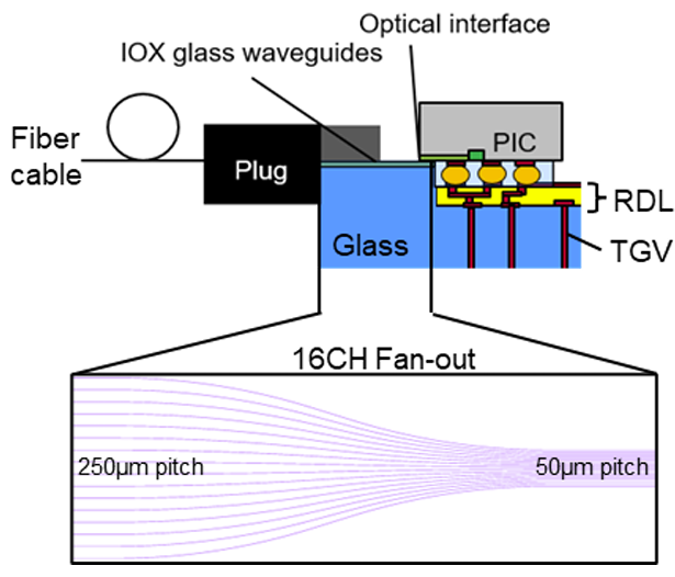
Corning's answer is to put electrical and optical functions on the same glass substrate: optical waveguides are formed in the glass by ion exchange, while thin-film electrical traces are built in etched trenches. PICs are flip-chip mounted and evanescently coupled to the glass waveguides, then connected to the redistribution layer (RDL) via electrical microbumps. This architecture—an electronic IC surrounded by multiple PICs linked by electrical traces a few millimeters long—combined with glass's panel-scale manufacturability, smooth surface and thermomechanical stability, is the stage for this paper.
We covered the glass-as-CPO-substrate race in full in Glass Substrates Are No Longer Slideware: Why the TGV Race Comes Together in 2026—that article examined the electrical value of TGV (through-glass vias), while this Corning paper fills in the “optical value” of the same piece of glass. The two are really two sides of the same coin.
2. The Core Problem: The Whole Paper in One Sentence
The problem this paper sets out to solve fits in one sentence: how to build a glass optical waveguide platform that sits next to 110°C heat without optical degradation for five years, can be mass-produced with panel-level processes, and delivers both low coupling loss and a small footprint.
Note that this sentence packs in four mutually conflicting conditions—thermal stability, manufacturability, low loss and small size. None is hard on its own; the difficulty is making all of them hold at once. The paper's three-part argument (specialty glass, low-loss straight waveguides, compact bend design) takes these four constraints apart one by one.

3. Key Figures, One by One
3.1 This Figure Shows “Why the Glass Must Change”—Thermal Stability Is the Line Between Life and Death
This figure (Figure 3) is the soul of the paper. It compares how the waveguide index contrast (Δn) of the specialty CPO glass and an unoptimized commercial glass changes over service life at 110°C. The conclusion is sharp enough to need no interpretation: commercial glass fails within the first month, while the specialty CPO glass shows less than 1.5% index change after five years.
The physics behind it: when a CPO compute chip is running, the glass sits at about 110°C, which keeps silver ions (Ag⁺) in the ion-exchanged waveguide diffusing outward. The refractive index drops and the mode field expands, so fiber-to-waveguide coupling efficiency collapses, loss soars, and the device eventually fails. The only way to stop this is to find a glass with sufficiently low silver-ion diffusivity. Corning set the threshold at a diffusivity below 2E-21 m²/s at 110°C to meet the data center requirement of at least five years of lifetime.

3.2 This Figure Shows “How Deep Corning's Moat Is”—Only a Few of 200 Compositions Pass
This figure (Figure 2) plots the silver-ion diffusivity at 110°C of more than 200 alkali-containing glasses. Only the few compositions inside the green box meet the <2E-21 m²/s target, and the red dot marks the specialty CPO glass used in this paper.
The figure looks unremarkable, but it is the real barrier to entry. Anyone can design waveguides; screening 200 glass compositions while simultaneously meeting high liquidus viscosity (required for panel-scale forming), Δn > 0.025 after the first silver ion exchange, and ultra-low diffusivity is something only a company with glass melting lines and a materials database can pull off. In its conclusion, Corning updates the number to something even more striking: the final glass has a silver-ion diffusivity of about 5E-22 m²/s, a notch below its own threshold.

3.3 This Figure Shows a Counterintuitive Design: “Tighter Bends, Lower Loss”

This figure (Figure 6) compares measured and simulated insertion loss of 90° bent waveguides at 1310 nm. The key point: once the bend radius drops below 10 mm, simply widening the mask opening in the bend section actually lowers the loss.
This defies the usual intuition that tighter bends mean higher loss. Corning's trick: during the first ion exchange, it widens the mask opening in the bend section so that more silver ions diffuse in, locally raising the index contrast and strengthening mode confinement, so even tight bends keep loss low. This is the paper's core innovation—low index contrast in straight sections (for easy fiber coupling), high index contrast in bend sections (for compact tight bends), linked by mode-matching transition sections. The result: bend loss drops from 4 dB/cm to 0.01 dB/cm at a 10 mm bend radius.
3.4 This Figure Shows “What a Manufacturable Product Looks Like”—A 16-Channel Fan-Out

This figure (Figure 7) shows the measured insertion loss of a 16-waveguide glass fan-out device. The waveguides are S-bends with offsets that convert the fiber connector pitch to the PIC's dense pitch.
This is product-level validation that ties all the preceding techniques together. Corning used two sets of 16 S-bend waveguides (6 mm and 8 mm) to convert pitch from 250 µm to 50 µm and 127 µm, with both Euler-bend and circular-bend designs, spatially varying Δn enhancement in the bend sections, and lateral offsets tuned for minimum loss. The Euler bend achieved a 6 mm minimum bend radius (11.5 mm equivalent), the circular bend 9.9 mm. Over a total length of about 12.5 cm, measured fiber-to-fiber losses were 0.62±0.01 dB and 0.65±0.04 dB, breaking down into <0.3 dB coupling per facet, 0.04 dB/cm propagation and about 0.01 dB/cm bend loss. Compared with uniform-Δn waveguides, the optimized fan-out cuts loss by up to 1.3 dB at the smallest bend radii, on channels 1 and 16.
4. Technical Highlights: Two Points Truly Worth Remembering
The first highlight is the ultra-low silver-ion diffusion glass at the materials level. This is not parameter tweaking—it directly eliminates CPO's most lethal weakness in thermal reliability. Conventional IOX glass degrades within a month at 110°C, while Corning's glass shows <1.5% index change over five years with a diffusivity of about 5E-22 m²/s. For a component that must sit next to a high-speed ASIC and meet a five-year data center lifetime requirement, this is the difference between “can it go on the production line” and “can't,” not between good and better.
The second highlight is the segmented index-contrast waveguide technique at the design level. Using mask opening width to locally control ion-exchange concentration amounts to building a gradient design on a single waveguide—low contrast at the fiber-coupling end, high contrast at the tight bends—while the glass's own diffusion characteristics naturally form smooth straight-to-bend transitions. This gives Corning two normally mutually exclusive benefits at once, low coupling loss and small device size: straight-waveguide propagation loss of 0.041 dB/cm (best 0.0397) and fiber coupling loss of 0.28 dB (close to the simulated 0.3 dB, coupled to Corning's own SMF-28 Ultra fiber).
Notably, the polymer waveguide route we discussed in Technical Analysis | Polymer Waveguides Withstand +20 dBm for Six Hours: The Missing “Optical Redistribution” Piece for ELS-Based CPO is another materials answer to the same “straight-bend segmented optimization” challenge—glass bets on thermal reliability and panel-scale production, polymer on low cost and flexibility. Both routes are solving the same “optical redistribution” piece of the CPO puzzle.
5. Industry Implications: How Far from Volume Production? Who Benefits?
First, the distance. This paper is a level more mature than most academic work: it runs the full process on 150 mm wafers of 0.7 mm-thick glass, laser-cuts the optical end faces, and averages measurements over 14 waveguides, with a standard deviation held below 0.03 dB. This is not a one-off lab miracle but engineering validation with statistical distributions and panel-scale process intent. In other words, Corning isn't after a paper—it wants to prove “this can go on a production line.” On the road to commercial CPO, the glass waveguide piece has reached process-integration validation; what remains is system integration with PIC flip-chip, detachable fiber connectors and overall package yield.
Now the beneficiaries. The most direct is the glass substrate ecosystem—when both electrical (TGV) and optical (IOX waveguide) functions can be built on the same piece of glass, glass shifts from “candidate material” to an integration platform serving as the shared CPO substrate, a theme for glass materials, panel-level equipment and related packaging houses. Second is detachable fiber connectors: the paper explicitly makes “a mechanically isolated fiber array connector attached at the end of the process” an architectural premise, which is exactly the hidden gating item for CPO volume production. We took full stock of it in The Great Shift in Optical Packaging (Part 5): The Detachable Fiber Battle, CPO's Hidden Gating Item for Volume Production. Third, it offers a contrast with low-cost CPO approaches based on fan-out packaging—the glass route competes on thermal reliability and integration, while the fan-out route competes on driving down cost with mature production lines.
A note of caution: for glass substrates to truly win the CPO substrate market, they must take on silicon interposers and organic substrates, whose ecosystems, equipment depreciation and customer relationships are far more mature than glass. Corning's paper proves that glass has a unique advantage in optics and thermal reliability, but turning an “advantage” into “market share” still requires clearing three real-world barriers: yield, cost and customers' willingness to adopt.
6. Conclusion
The single sentence most worth remembering from this paper: Corning's real weapon is not waveguide design, but a glass screened from 200 compositions that others cannot replicate in the short term. The segmented index-contrast design is elegant, 0.01 dB/cm bend loss is impressive, and a 0.62 dB 16-channel fan-out is practical—but all of it is built on the foundation of “5E-22 m²/s silver-ion diffusivity and <1.5% Δn change over five years.” And that foundation is the accumulation of materials science, not a clever design trick.
For anyone tracking the CPO supply chain, this provides a clear checkpoint: when assessing the CPO competitiveness of a glass substrate, don't just look at waveguide loss numbers—ask how many years its glass can last at 110°C. Thermal reliability is the invisible barrier keeping lab results out of volume production, and it is precisely the deepest moat of a century-old glass company like Corning. As optical communications evolves from a growth-stock theme into core AI infrastructure, whoever holds “materials no one else can make” holds the hardest position to replace.
References
Lars Brusberg, Jorge Holguin-Lerma, Matthew J. Dejneka, Lucas W. Yeary, Chad C. Terwilliger, Betsy J. Johnson, Charisse Spier, Jonathan E. Walter, Katerina Rousseva, Sean M. Garner, "Low-Loss Optical Interconnect Designs in Optimized Glass for Co-Packaged Optics," 2026 IEEE 76th Electronic Components and Technology Conference (ECTC), pp. 628–631. DOI: 10.1109/ECTC51846.2026.00106
Corning Optical Communication GmbH & Co. KG (Berlin, Germany) and Corning Research and Development Corporation (Corning, New York, USA)
Further references: Brusberg et al., "Glass platform for co-packaged optics," IEEE JSTQE 29(3), 2023; Brusberg et al., "Optical design and applications for ion-exchanged glass waveguide circuits," IEEE TCPMT, 2025
Related Reading
Glass Substrates Are No Longer Slideware: Why the TGV Race Comes Together in 2026: the electrical value of the same piece of glass—the other side of the optical value discussed here
The Great Shift in Optical Packaging (Part 5): The Detachable Fiber Battle, CPO's Hidden Gating Item for Volume Production: a full review of the detachable fiber connectors this article's architecture relies on
Building a 1.6T Optical Engine with Fan-Out Packaging: Singapore A*STAR's Low-Cost CPO Approach: another low-cost CPO substrate approach beyond the glass route


Comments