


ECTC 2026 | Keio University | Low-Loss Polymer Waveguide Device for Fiber-to-Chip and Chip-to-Chip Connection
At ECTC 2026, Keio University used a process called the "Mosquito method" — injecting core material into the cladding through a fine needle, much like a mosquito's proboscis — to build ultra-low-loss single-mode polymer waveguides. The key is that it produces a graded-index (GI) circular core that confines light through its refractive-index profile rather than through total internal reflection at a core-cladding interface, eliminating scattering loss from interface roughness. The result: propagation loss at 1310 nm of only 0.22–0.35 dB/cm, approaching the material's intrinsic limit (Ormocer, ~0.23 dB/cm); an 8 cm waveguide carries 106 Gb/s (53 Gbaud PAM4) with a clean eye and a TDECQ of 1.72 dB — even better than without the waveguide. Better still, using fluid-dynamics analysis, the team built a four-core array at 20 µm pitch — more than ten times finer than the needle's outer diameter — with extremely low crosstalk. In one sentence: by "drawing" light paths into polymer with a single needle, Keio has built CPO optical redistribution that approaches the material limit.
1. Background: CPO optical redistribution needs a more flexible waveguide process
This paper comes from the Ishigure Lab at Keio University in Japan and was presented at the 2026 IEEE 76th ECTC. CPO and chiplet systems need an optical redistribution layer (ORDL) for fan-in/fan-out pitch conversion, but today's planar waveguides (such as adiabatic couplers) are constrained by core cross-section geometry and routing layout, limiting design flexibility and performance scaling.
The Mosquito method developed at Keio is a polymer waveguide process: a fine needle injects core monomer into cladding monomer, and simply scanning the needle's path can draw arbitrary 3D core routes. During the "interim time" between injection and UV exposure, the core and cladding monomers interdiffuse to form a graded-index (GI) circular core. This gives a high degree of design freedom.
We have covered polymer waveguides as a CPO optical redistribution route in both Technical paper analysis | A polymer waveguide withstands +20 dBm for six hours and Taking on 1.6T optical engines with fan-out packaging: A*STAR's low-cost CPO approach — what this Keio paper contributes is two material/process metrics: "low loss + fine pitch."

2. The core question: the whole paper in one sentence
What this paper sets out to prove is: whether a GI circular-core polymer waveguide made with the Mosquito method can simultaneously achieve near-material-limit low loss, 106 Gb/s high-speed transmission, and a pitch as fine as 20 µm with low crosstalk.
The answer is that it achieves all three — and the low loss comes from the GI core avoiding interface scattering.
3. Key figures, one by one
3.1 This figure shows "why a GI core can approach the material limit"
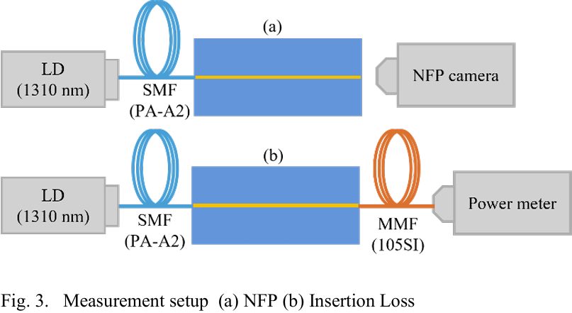
These figures (Fig. 1, Fig. 3) address the sources of loss. A conventional step-index (SI) waveguide confines light by total internal reflection at the core-cladding interface, and interface roughness adds extra scattering loss, so total loss = material loss + structural loss. The GI core made by the Mosquito method confines light by refraction through its index profile, so structural (interface) scattering loss is minimized. The result: propagation loss of 0.22–0.35 dB/cm at 1310 nm, approaching the intrinsic absorption of Ormocer (an organic-inorganic hybrid resin), ~0.23 dB/cm. Ormocer has fewer C-H bonds (especially aliphatic C-H) than typical hydrocarbon polymers, so its intrinsic absorption is low to begin with.
Key point: the low loss doesn't come from the material doing all the work — it comes from the GI structure driving the "structural loss" term to nearly zero.
3.2 This figure shows "106 Gb/s passes — with an even better TDECQ"
These figures (Fig. 5, Table III) are eye diagrams. The low-loss waveguide was run at 1310 nm, 106 Gb/s (53 Gbaud PAM4), over 8 cm. The result: TDECQ of 1.72 dB with the waveguide versus 1.93 dB without it (direct connection) — adding the waveguide actually made it better. The waveguide has a wide low-loss window across the O-band (1.26–1.32 µm) and can support 4–8 wavelength WDM, helping address the "shoreline density" problem of fiber-to-chip coupling.

3.3 This figure shows "20 µm pitch breaking the needle-size limit"

These figures (Fig. 7, Table IV) cover the fine-pitch array. Intuitively, with a needle outer diameter more than ten times the 20 µm pitch, scanning the needle for a later core should disturb the cores injected earlier. But Keio's fluid-dynamics analysis shows that the earlier-injected core monomer flows around the needle's outer wall to avoid disturbance and returns almost to its original position after the needle passes — so a four-core array at 20 µm pitch can be made without being limited by needle size. After 7.5 cm of transmission, there is virtually no light leaking into adjacent cores and crosstalk is extremely low (the OrmoCore/OrmoClad index contrast is large enough to tightly confine the mode in the core). The team is now working on fan-outs between 20 µm and 127 µm pitch and aims to push to 10 µm pitch.
4. Technical Highlights
The first highlight is that the GI circular core drives structural scattering loss to zero: the Mosquito diffusion process creates a graded-index core that avoids interface-roughness scattering, bringing propagation loss close to the material's intrinsic 0.23 dB/cm. That is a rare level of low loss for a polymer waveguide.
The second highlight is using fluid dynamics to beat the needle-size limit and achieve 20 µm fine pitch: proving that later-injected cores don't disturb earlier ones, the team built an array more than ten times finer than the needle diameter, with low crosstalk. This extends the Mosquito method's design flexibility into high density — key for ORDL fan-in/fan-out and chiplet interconnect.
5. Industry Link: How far from volume production? Who benefits?
Distance: this is at the "material/process validation" stage — an academic lab result. Loss, 106 Gb/s transmission and the 20 µm array have all been verified, but there is still a way to go before line integration (interfacing with PICs/FAUs, volume yield, turning the Mosquito method into production equipment). Keio says its next steps are 20/127 µm fan-outs and pushing to 10 µm pitch.
Beneficiaries: most directly, the polymer ORDL and related materials (Ormocer-type) ecosystem; next, packaging researchers and vendors who want "high design freedom, low loss and arbitrary 3D routing" for CPO optical redistribution or chiplet optical interconnect. A sober note: the Mosquito method is a serial process that writes one needle path at a time, so volume throughput and equipment readiness are the issues it must face against parallel processes such as DNP's imprinting and Qnity's dry film — it wins on flexibility and low loss, and production takt time is its open question.
6. Conclusion
The one sentence to remember from this paper: by "drawing" light paths into polymer with a single needle and using a GI core to avoid interface scattering, Keio built a single-mode waveguide approaching the material limit (0.22–0.35 dB/cm), and used fluid dynamics to achieve a 20 µm fine-pitch array. For anyone tracking CPO optical redistribution, the thing to watch is that the polymer waveguide route competes on "low loss × design freedom × fine pitch × volume throughput." The Mosquito method is strong on the first three; production takt time is the next hurdle it has to prove.
References
Kai Yokoyama, Haruka Nakajima, Takaaki Ishigure, "Low-Loss Polymer Waveguide Device for Fiber-to-Chip and Chip-to-Chip Connection," 2026 IEEE 76th ECTC. Keio University, Yokohama, Japan.
Related Reading
Technical paper analysis | A polymer waveguide withstands +20 dBm for six hours: high-power reliability on the polymer waveguide route
Taking on 1.6T optical engines with fan-out packaging: A*STAR's low-cost CPO approach: another approach to integrating optical redistribution into the package


Comments